Introduction: Harbor Freight Grinder Rescue
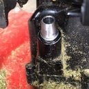
This is a Harbor Freight angle head grinder. It is not their least expensive, nor their most expensive grinder, but a mid-range choice that sells for around $35 US. It works well, but has a weakness. See the second photo. Note the red arrow. It indicates the location of a break in the plastic linkage from the electrical switch to the yellow switch button visible in the first photo. Once the plastic linkage breaks, the grinder is useless. In the second photo you can also see the steel linkage I made to replace the plastic linkage and restore function to my grinder. This Instructable will describe how I made and fitted the steel linkage. It will also provide an option for those who do not have access to a welder.
Materials
- Steel 1/16" (about 1.6mm) thick
- Steel 1/8" (about 3mm) thick
Tools
- Phillips screwdriver
- Drill
- Small file
- Hacksaw
- Grinder
Step 1: Open the Grinder
Remove the single screw near where the power cord enters the case and slide the half of the case on the power cord end away from the motor. See the second photo. Remove the wheel guard. Then remove the four screws holding the metal head on the grinder. Two are encircled in red. Two are not visible, but their approximate location is indicated by the red arrows.
Step 2: The Switch
Note the text box in the photo. If you do not have access to a welder so you can make a steel linkage to replace the plastic linkage, you can mount a replacement toggle or twist switch on the bottom half of the case where you can find space. Connect to the two wires shown in the photo.
Step 3: Steel Linkage
I tried to replicate the broken plastic linkage as closely as possible with my replacement steel linkage, but there were limitations. The yellow switch button requires a square hole for a fitting. I drilled two holes and used a small file to make it rectangular. See the text boxes. Some improvising was needed. I also left an open door for myself so I could make small adjustment to the length of the linkage. After making and installing the steel linkage, I used some grinding to smooth the linkage so it releases as it should. Still, that is better after some usage. Lubrication with some paraffin rubbed on the steel helps, too.
See the second photo. A plastic linkage does not conduct electricity, so there is no danger it will short leads and terminals. But, a steel linkage is a different situation. I thinned the width of the steel linkage so it would not wear on the insulation for the wires and create an electrical short.
Step 4: Reassembly
When I made and installed my steel linkage, I had to remove the motor's armature. That meant the commutator had to come out of the brush assembly. Getting the commutator back between the two brushes is very difficult. I could hold one brush back out of the way, but finally removed the brush holder screws on the second brush and put the brush holder back in place afterward. See the second photo and the text box.
This angle head grinder need not be considered a cheap throw away item. I use it quite a lot. That would not be possible if I had not replaced the weak plastic linkage with a sturdy steel linkage. I use this grinder with a cut off wheel most of the time. I do not use it continuously for long periods. So, mine has plenty of time to cool. It will continue to serve me well for a long time.
Step 5: After the Yellow Button
After a few years of use, the yellow switch button fell away from the grinder and would not stay in place. I decided to replace the switch button with a lever I squeeze while holding the grinder. It is a big improvement. I never use the screw-in side handle. I broke it apart and saved the bolt inside. I cut the bolt to length and use it to hold my switch lever. The switch lever has a pin about which it can swivel when the lever is depressed. A rectangular tooth extends down into the grinder to catch the hole where the yellow button had been. I have thought about adding a spring-loaded flip lever that copies commercial switches like this to keep the grinder from coming “on” when not intended. I can unplug it when not in use until I make a successful flip safety lever.
This worked very well for quite a while. Then I got an electrical shock from the steel switch handle. The part of the handle that reaches inside the grinder scraped the field windings of the motor. See the bare copper spot in the second photo. I tried grinding the part of the handle that protrudes into the motor case, but could not get a consistent solution to the problem. See the next step.
Step 6: A New Linkage
I made a switch lever that anchors solidly to one of the threaded holes in the gearhead. Normally that hole would be for a screw-in handle, but I do not use one. I drilled a hole from the back of the case toward the pushbutton on the switch inside. It needs an extra “L” connector with hinged joints to work smoothly. I added a rod guard to keep the switch handle from opening far enough to let the pushrod become misaligned. A little oil on the hinge joints helps make the action smooth. It is a bit more complicated than I like, but works well. See also text boxes.


